Industrial Protocols
Purple Pi OH2 Modbus MQTT CANbus
Learning industrial communication protocols such as CAN Bus, Modbus, and MQTT on the Purple Pi enables reliable integration between embedded devices, industrial equipment, and cloud systems. By configuring interfaces like UART, SPI, and network services, the Purple Pi can act as a bridge between field-level devices and higher-level applications. Mastering these protocols provides a strong foundation for building scalable IoT and industrial automation solutions.
Modbus RTU with Purple Pi OH2
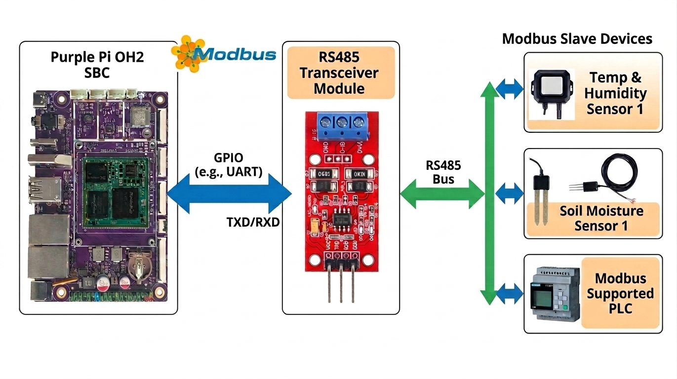
Overview of Modbus RTU
Modbus RTU is a widely used serial communication protocol in industrial automation systems. It enables reliable communication between controllers, sensors, actuators, and other field devices over simple physical layers such as RS-485. Its simplicity, robustness, and vendor-neutral design make it a standard choice in industrial environments.
Why Modbus RTU
Modbus RTU is designed for deterministic and reliable communication in noisy industrial environments. It operates over RS-485, which supports long cable distances and multi-drop configurations. Due to its simplicity and low overhead, it is efficient for real-time control and monitoring applications.
Connecting Purple Pi OH2 to Modbus RTU
The Purple Pi OH2 can communicate with Modbus RTU devices using its UART interface combined with an RS-485 transceiver module. Since Modbus RTU commonly runs over RS-485, a UART-to-RS485 converter is required to bridge the hardware interface.
Prerequisites
- Purple Pi OH2 board
- UART to RS-485 converter module (MAX13487E recommended)
- RS-485 to USB adapter (for testing with PC)
- Modbus Slave software: https://www.modbustools.com/download.html
- Python 3 environment
- Basic understanding of serial communication
Hardware Components
- RS485-UART Converter Board based on MAX13487E
- USB to RS485 converter for PC-side simulation/testing
Connection Overview
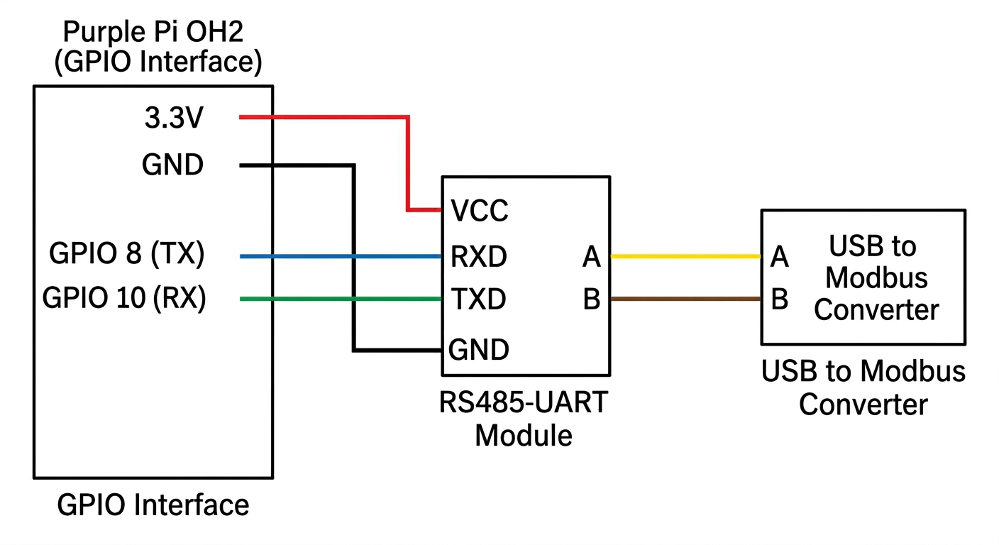
Connect the RS485-UART converter to the Purple Pi OH2 GPIO UART pins as follows:
For RS-485 bus wiring:
Ensure correct polarity; reversing A and B will prevent communication.
Modbus Slave Software Configuration
- Install and open Modbus Slave software on your PC
- Select the correct COM port (connected via RS485-USB adapter)
-
Configure serial settings:
-
Baud rate: 115200
- Data bits: 8
- Parity: None
- Stop bits: 1 (8N1)
- Set the slave ID (e.g., 1)
- Configure holding registers for testing
Software Setup on Purple Pi OH2
Create Project Directory
Create and Activate Virtual Environment
Install Required Libraries
Modbus RTU Test Script
Create a file named modbus_server_purplepi.py:
#!/usr/bin/env python3
import minimalmodbus
import serial
import time

# --- Configuration ---
PORT = '/dev/ttyS7'
SLAVE_ADDRESS = 1
BAUDRATE = 115200
BYTESIZE = 8
PARITY = serial.PARITY_NONE
STOPBITS = 1
TIMEOUT = 0.5

# --- Register to Read ---
REGISTER_ADDRESS = 0
NUMBER_OF_REGISTERS = 1
FUNCTION_CODE = 3

# --- Create instrument object ---
try:
    instrument = minimalmodbus.Instrument(PORT, SLAVE_ADDRESS)
    instrument.serial.baudrate = BAUDRATE
    instrument.serial.bytesize = BYTESIZE
    instrument.serial.parity = PARITY
    instrument.serial.stopbits = STOPBITS
    instrument.serial.timeout = TIMEOUT
    instrument.mode = minimalmodbus.MODE_RTU
    instrument.clear_buffers_before_each_transaction = True

    print(f"Attempting to communicate with Modbus slave ID {SLAVE_ADDRESS} on {PORT}...")
    print(f"Serial settings: {BAUDRATE} baud, {BYTESIZE}{PARITY}{STOPBITS}")
    print("-" * 40)

except Exception as e:
    print(f"Error setting up serial port: {e}")
    exit(1)

# --- Test Communication ---
try:
    print("Reading holding registers...")
    values = instrument.read_registers(
        registeraddress=REGISTER_ADDRESS,
        number_of_registers=NUMBER_OF_REGISTERS,
        functioncode=FUNCTION_CODE
    )

    print(f"Successfully read {NUMBER_OF_REGISTERS} register(s) starting at address {REGISTER_ADDRESS}:")
    for i, val in enumerate(values):
        print(f"  Register {REGISTER_ADDRESS + i}: {val} (0x{val:04X})")

except minimalmodbus.NoResponseError:
    print(f"ERROR: No response from device {SLAVE_ADDRESS}.")
    print("Check:")
    print(f"  - Is the device powered and connected to {PORT}?")
    print(f"  - Is the slave address correct?")
    print(f"  - Are the baud rate and serial settings correct?")
    print("  - Is the register address valid and readable?")

except minimalmodbus.InvalidResponseError as e:
    print("ERROR: Invalid response received.")
    print(f"Details: {e}")

except Exception as e:
    print(f"Unexpected error: {e}")

finally:
    if instrument.serial:
        instrument.serial.close()
        print("Serial port closed.")
Permissions Setup
Add your user to the dialout group to access serial ports:
After running this command:
- Close all terminals and VS Code
- Log out and log back in (or reboot)
Running the Application
Reactivate your virtual environment:
Run the script:
Notes and Troubleshooting
- Ensure
/dev/ttyS7matches your actual UART device - Verify wiring, especially A/B polarity
- Confirm baud rate and slave ID match the Modbus Slave software
- Use proper grounding to avoid noise-related errors
- Enable debug mode in
minimalmodbusif deeper inspection is needed
Conclusion
This setup demonstrates a basic Modbus RTU master implementation using the Purple Pi OH2. It can be extended to interact with PLCs, industrial sensors, and other Modbus-compatible devices for real-world automation applications.
MQTT Basics and Setup Guide
What is MQTT?
MQTT (Message Queuing Telemetry Transport) is a lightweight messaging protocol designed for communication between devices, especially in IoT systems. It uses a publish–subscribe model, making it efficient for low-bandwidth and unreliable networks.
Advantages of MQTT
- Lightweight protocol – Uses minimal bandwidth, making it ideal for IoT and embedded devices.
- Efficient communication – Publish/subscribe model reduces direct device-to-device communication overhead.
- Reliable message delivery – Supports different Quality of Service (QoS) levels for message assurance.
MQTT Components
Client
A client is any device or application that sends (publishes) or receives (subscribes to) messages in the MQTT system.
Connection
A connection is the network link established between a client and the broker using TCP/IP.
Broker
The broker is the central server that receives messages from publishers and distributes them to subscribers based on topics.
How MQTT Works
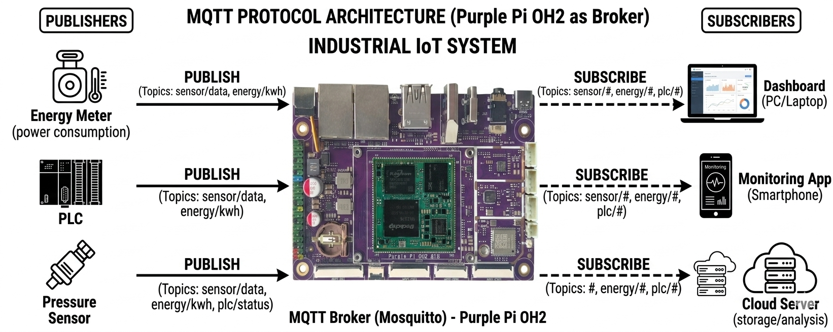
MQTT works using a publish–subscribe communication model where clients do not communicate directly with each other. A publisher sends a message to a specific topic on the broker. The broker then forwards that message to all clients subscribed to that topic. This decouples devices, making the system scalable and efficient.
Setting Up Purple Pi OH2 as an MQTT Broker
Step 1: Install Mosquitto
Step 2: Enable Mosquitto Service
Step 3: Run Mosquitto Broker
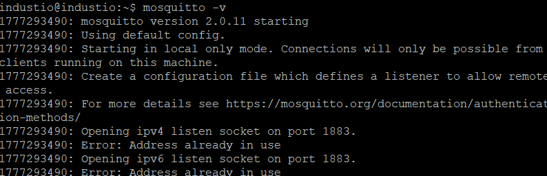
Enable Remote Access (No Authentication)
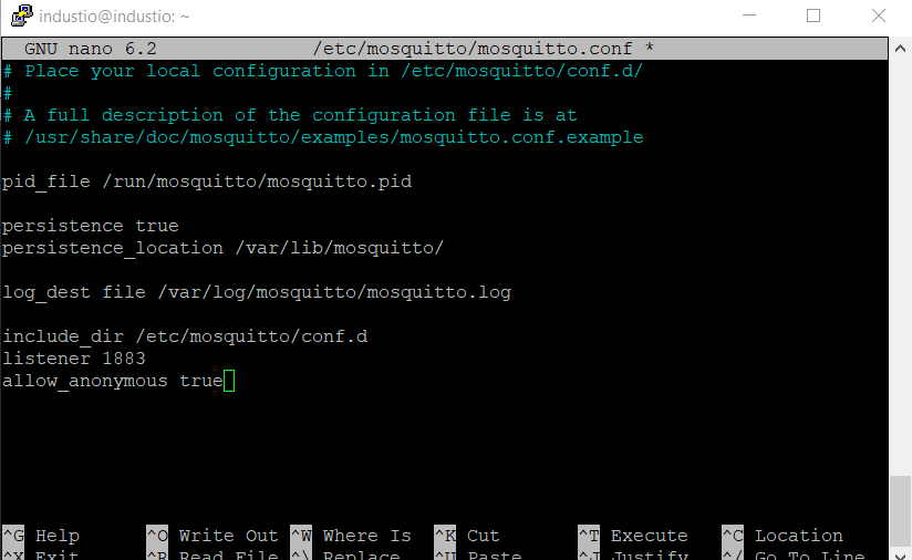
Step 4: Edit Configuration File
Add the following at the end of the file:
Save and exit:
- Press
CTRL + X - Press
Y - Press
Enter
Step 5: Restart Mosquitto
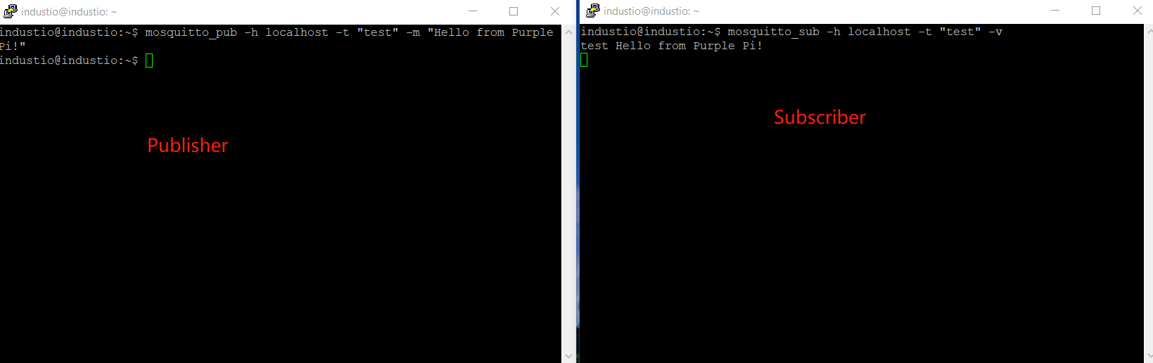
Testing MQTT Communication
Terminal 1 (Subscriber)
Terminal 2 (Publisher)
Expected Result
The message published from Terminal 2 should appear in Terminal 1.

Notes
- Port
1883is the default MQTT port. allow_anonymous trueis useful for testing but not recommended for production due to security risks.
CAN Bus with Purple Pi OH2
What is CAN Bus?
CAN (Controller Area Network) is a robust, message-based communication protocol originally developed for automotive applications and now widely adopted in industrial automation, robotics, medical equipment, and IoT. It uses a differential two-wire bus (CAN_H and CAN_L) that provides excellent noise immunity, making it ideal for harsh industrial environments where electrical interference is common.
Unlike master-slave protocols, CAN is multi-master — any node can transmit when the bus is idle. Messages are identified by a unique CAN ID rather than a node address, so receivers can subscribe only to the data they need.
Why Use CAN Bus
- High noise immunity – Differential signaling rejects electromagnetic interference.
- Multi-master architecture – Any node can transmit; no single master bottleneck.
- Priority-based messaging – Lower CAN IDs have higher priority, ensuring critical data gets through first.
- Long cable distances – Supports bus lengths up to 1 km at lower bitrates.
- Reliable error detection – Built-in CRC, acknowledgement, and error frames detect and signal faults automatically.
- Cost-effective – Only two wires plus ground are needed for the entire network.
Prerequisites
- Purple Pi OH2 board
- MCP2515 CAN module with TJA1050 transceiver
- Arduino (optional) – for generating CAN traffic / testing
- Dupont wires (at least 6 female-to-female)
- 120 Ω termination resistor (if not built into the module)
Hardware Wiring
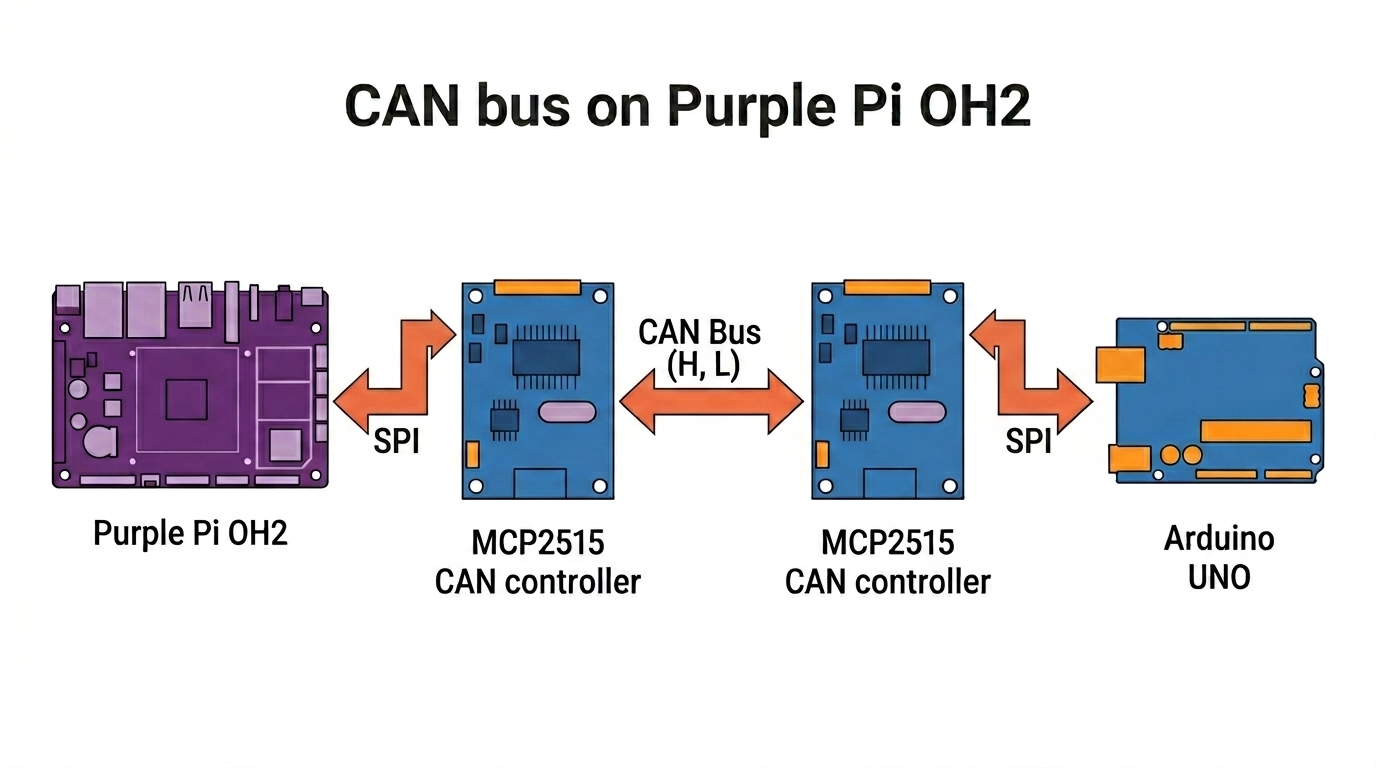
Connect the MCP2515 module to the Purple Pi OH2 40-pin header:
| Purple Pi OH2 | MCP2515 Module | Function |
|---|---|---|
| Pin 19 | SI | SPI MOSI |
| Pin 21 | SO | SPI MISO |
| Pin 23 | SCK | SPI Clock |
| Pin 26 | CS | SPI Chip-Select 1 |
| Pin 2 | VCC | 5V (TJA1050 transceiver requires 5V) |
| Pin 6 | GND | Ground |
| — | CAN_H | To CAN bus high |
| — | CAN_L | To CAN bus low |
Power note: The MCP2515 logic operates at 3.3V, but the TJA1050 transceiver must be powered from 5V (Pin 2) to generate correct differential signals on CAN_H/CAN_L. Powering from 3.3V will allow SPI communication but the CAN bus side will fail.
Connect the CAN bus differential pair:
Place a 120 Ω resistor across CAN_H and CAN_L at each end of the bus.
Software Setup on Purple Pi OH2
Create Project Directory
Create and Activate Virtual Environment
Install Required Libraries
Fix SPI Permissions
MCP2515 Driver
Create mcp2515_driver.py:
#!/usr/bin/env python3
"""
MCP2515 CAN Controller Driver - Purple Pi OH2 Version
SPI0 Bus, CS1 (Pin 26) → /dev/spidev0.1
"""

import spidev
import time

# ── SPI Commands ──────────────────────────────────────────────────────────────
MCP2515_RESET       = 0xC0
MCP2515_READ        = 0x03
MCP2515_WRITE       = 0x02
MCP2515_RTS         = 0x80
MCP2515_BIT_MODIFY  = 0x05
MCP2515_READ_STATUS = 0xA0
MCP2515_RX_STATUS   = 0xB0

# ── Registers ─────────────────────────────────────────────────────────────────
CANCTRL  = 0x0F
CANSTAT  = 0x0E
CNF1     = 0x2A
CNF2     = 0x29
CNF3     = 0x28
CANINTE  = 0x2B
CANINTF  = 0x2C
EFLG     = 0x2D

TXB0CTRL = 0x30
TXB0SIDH = 0x31
TXB0SIDL = 0x32
TXB0EID8 = 0x33
TXB0EID0 = 0x34
TXB0DLC  = 0x35
TXB0DATA = 0x36

RXB0CTRL = 0x60
RXB0SIDH = 0x61
RXB0SIDL = 0x62
RXB0EID8 = 0x63
RXB0EID0 = 0x64
RXB0DLC  = 0x65
RXB0DATA = 0x66

RXB1CTRL = 0x70
RXB1SIDH = 0x71
RXB1SIDL = 0x72
RXB1EID8 = 0x73
RXB1EID0 = 0x74
RXB1DLC  = 0x75
RXB1DATA = 0x76

# ── Operating Modes ───────────────────────────────────────────────────────────
MODE_NORMAL     = 0x00
MODE_SLEEP      = 0x20
MODE_LOOPBACK   = 0x40
MODE_LISTENONLY = 0x60
MODE_CONFIG     = 0x80

# ── Bitrate Tables (exact values from Arduino mcp2515.h) ──────────────────────
CAN_SPEED_8MHZ = {
    1000000: [0x00, 0x80, 0x80],
    500000:  [0x00, 0x90, 0x82],
    250000:  [0x00, 0xB1, 0x85],
    200000:  [0x00, 0xB4, 0x86],
    125000:  [0x01, 0xB1, 0x85],
    100000:  [0x01, 0xB4, 0x86],
    80000:   [0x01, 0xBF, 0x87],
    50000:   [0x03, 0xB4, 0x86],
    40000:   [0x03, 0xBF, 0x87],
    33333:   [0x47, 0xE2, 0x85],
    31250:   [0x07, 0xA4, 0x84],
    20000:   [0x07, 0xBF, 0x87],
    10000:   [0x0F, 0xBF, 0x87],
    5000:    [0x1F, 0xBF, 0x87],
}

CAN_SPEED_16MHZ = {
    1000000: [0x00, 0xD0, 0x82],
    500000:  [0x00, 0xF0, 0x86],
    250000:  [0x41, 0xF1, 0x85],
    200000:  [0x01, 0xFA, 0x87],
    125000:  [0x03, 0xF0, 0x86],
    100000:  [0x03, 0xFA, 0x87],
    95000:   [0x03, 0xAD, 0x07],
    83333:   [0x03, 0xBE, 0x07],
    80000:   [0x03, 0xFF, 0x87],
    50000:   [0x07, 0xFA, 0x87],
    40000:   [0x07, 0xFF, 0x87],
    33333:   [0x4E, 0xF1, 0x85],
    20000:   [0x0F, 0xFF, 0x87],
    10000:   [0x1F, 0xFF, 0x87],
    5000:    [0x3F, 0xFF, 0x87],
}

CAN_SPEED_20MHZ = {
    1000000: [0x00, 0xD9, 0x82],
    500000:  [0x00, 0xFA, 0x87],
    250000:  [0x41, 0xFB, 0x86],
    200000:  [0x01, 0xFF, 0x87],
    125000:  [0x03, 0xFA, 0x87],
    100000:  [0x04, 0xFA, 0x87],
    83333:   [0x04, 0xFE, 0x87],
    80000:   [0x04, 0xFF, 0x87],
    50000:   [0x09, 0xFA, 0x87],
    40000:   [0x09, 0xFF, 0x87],
    33333:   [0x0B, 0xFF, 0x87],
}


class CANMessage:
    """CAN Message container."""

    def __init__(self, can_id=0, data=None, dlc=0, extended=False, rtr=False):
        self.can_id   = can_id
        self.data     = data if data else []
        self.dlc      = dlc if dlc else len(self.data)
        self.extended = extended
        self.rtr      = rtr

    def __repr__(self):
        if self.rtr:
            return f"ID: 0x{self.can_id:03X}  RTR  DLC: {self.dlc}"
        data_str = ' '.join(f'0x{b:02X}' for b in self.data[:self.dlc])
        ext = " [EXT]" if self.extended else ""
        return f"ID: 0x{self.can_id:03X}{ext}  DLC: {self.dlc}  Data: [{data_str}]"


class MCP2515:
    """
    MCP2515 CAN controller driver for Purple Pi OH2.
    Default: bus=0, device=None → auto-probe /dev/spidev0.1 then /dev/spidev0.0
    """

    def __init__(self, spi_bus=0, spi_device=None, spi_speed=1_000_000, crystal=8_000_000):
        if crystal == 16_000_000:
            self.speed_table  = CAN_SPEED_16MHZ
            self.crystal_name = "16 MHz"
        elif crystal == 20_000_000:
            self.speed_table  = CAN_SPEED_20MHZ
            self.crystal_name = "20 MHz"
        else:
            self.speed_table  = CAN_SPEED_8MHZ
            self.crystal_name = "8 MHz"
            if crystal != 8_000_000:
                print(f"⚠️  Unknown crystal {crystal/1e6} MHz → using 8 MHz table")

        if spi_device is None:
            spi_device = self._find_spi_device(spi_bus, spi_speed)

        self.spi = spidev.SpiDev()
        self.spi.open(spi_bus, spi_device)
        self.spi.max_speed_hz = spi_speed
        self.spi.mode = 0b00
        self.spi.lsbfirst = False

        print(f"🔧 MCP2515  /dev/spidev{spi_bus}.{spi_device}"
              f"  @{spi_speed//1000} kHz  crystal={self.crystal_name}")

    @staticmethod
    def _probe_spi_device(spi_bus, spi_device, spi_speed):
        probe = spidev.SpiDev()
        try:
            probe.open(spi_bus, spi_device)
            probe.max_speed_hz = spi_speed
            probe.mode = 0b00
            probe.lsbfirst = False
            probe.xfer2([MCP2515_RESET])
            time.sleep(0.01)
            status = probe.xfer2([MCP2515_READ, CANSTAT, 0x00])[2]
            ctrl = probe.xfer2([MCP2515_READ, CANCTRL, 0x00])[2]
            got = status & 0xE0
            print(f"  🔍 probe /dev/spidev{spi_bus}.{spi_device}: CANSTAT=0x{status:02X} (mode=0x{got:02X}), CANCTRL=0x{ctrl:02X}")
            return got == MODE_CONFIG
        except Exception as exc:
            print(f"  ⚠️  probe /dev/spidev{spi_bus}.{spi_device} failed: {exc}")
            return False
        finally:
            try:
                probe.close()
            except Exception:
                pass

    @staticmethod
    def _find_spi_device(spi_bus, spi_speed):
        for spi_device in (1, 0):
            if MCP2515._probe_spi_device(spi_bus, spi_device, spi_speed):
                print(f"  ✅ Found MCP2515 on /dev/spidev{spi_bus}.{spi_device}")
                return spi_device
        raise RuntimeError(f"No MCP2515 found on /dev/spidev{spi_bus}.0 or /dev/spidev{spi_bus}.1")

    def reset(self):
        self.spi.xfer2([MCP2515_RESET])
        time.sleep(0.01)

    def read_register(self, addr):
        return self.spi.xfer2([MCP2515_READ, addr, 0x00])[2]

    def read_registers(self, addr, count):
        return self.spi.xfer2([MCP2515_READ, addr] + [0x00] * count)[2:]

    def write_register(self, addr, value):
        self.spi.xfer2([MCP2515_WRITE, addr, value])

    def write_registers(self, addr, values):
        self.spi.xfer2([MCP2515_WRITE, addr] + list(values))

    def modify_register(self, addr, mask, value):
        self.spi.xfer2([MCP2515_BIT_MODIFY, addr, mask, value])

    def set_mode(self, mode):
        _NAMES = {
            MODE_NORMAL:     "NORMAL",
            MODE_SLEEP:      "SLEEP",
            MODE_LOOPBACK:   "LOOPBACK",
            MODE_LISTENONLY: "LISTEN-ONLY",
            MODE_CONFIG:     "CONFIG",
        }
        self.modify_register(CANCTRL, 0xE0, mode)
        time.sleep(0.01)
        got = self.read_register(CANSTAT) & 0xE0
        if got == mode:
            print(f"   ✅ Mode → {_NAMES.get(mode, f'0x{mode:02X}')}")
            return True
        print(f"   ❌ Mode change FAILED  expected=0x{mode:02X}  got=0x{got:02X}")
        return False

    def set_bitrate(self, bitrate):
        if bitrate not in self.speed_table:
            closest = min(self.speed_table, key=lambda x: abs(x - bitrate))
            print(f"⚠️  {bitrate} bps not in table → using closest {closest} bps")
            bitrate = closest

        cfg = self.speed_table[bitrate]

        if not self.set_mode(MODE_CONFIG):
            print("❌ Could not enter CONFIG mode")
            return False

        self.write_register(CNF1, cfg[0])
        self.write_register(CNF2, cfg[1])
        self.write_register(CNF3, cfg[2])

        c1, c2, c3 = (self.read_register(r) for r in (CNF1, CNF2, CNF3))
        if c1 == cfg[0] and c2 == cfg[1] and c3 == cfg[2]:
            print(f"   ✅ Bitrate {bitrate} bps  CNF=[0x{c1:02X}, 0x{c2:02X}, 0x{c3:02X}]")
            return True

        print(f"   ⚠️  CNF verify fail  expected=[0x{cfg[0]:02X},0x{cfg[1]:02X},0x{cfg[2]:02X}]"
              f"  got=[0x{c1:02X},0x{c2:02X},0x{c3:02X}]")
        return False

    def init(self, bitrate=125_000, mode=MODE_NORMAL, loopback=False):
        sep = "─" * 52
        print(f"\n{sep}")
        print("  MCP2515 init — Purple Pi OH2")
        print(sep)

        self.reset()
        print("✅ Reset")

        if not self.set_bitrate(bitrate):
            return False

        self.write_register(RXB0CTRL, 0x64)
        self.write_register(RXB1CTRL, 0x60)

        self.write_register(CANINTE, 0x03)
        self.write_register(CANINTF, 0x00)

        final_mode = MODE_LOOPBACK if loopback else mode
        if loopback:
            print("🔄 Loopback mode (self-test)")

        ok = self.set_mode(final_mode)
        print(f"{sep}")
        print(f"  {'✅ Init complete' if ok else '❌ Init FAILED'}")
        print(f"{sep}\n")
        return ok

    def send_message(self, msg, txbuf=0):
        _TX = [
            (TXB0CTRL, TXB0SIDH, TXB0DLC, TXB0DATA),
            (0x40,     0x41,     0x45,    0x46),
            (0x50,     0x51,     0x55,    0x56),
        ]
        txbuf = max(0, min(txbuf, 2))
        ctrl, sidh, dlc_reg, data_reg = _TX[txbuf]

        if self.read_register(ctrl) & 0x08:
            return False

        if msg.extended:
            self.write_register(sidh,     (msg.can_id >> 21) & 0xFF)
            self.write_register(sidh + 1, ((msg.can_id >> 13) & 0xE0) | 0x08 |
                                           ((msg.can_id >> 16) & 0x03))
            self.write_register(sidh + 2, (msg.can_id >> 8)  & 0xFF)
            self.write_register(sidh + 3,  msg.can_id        & 0xFF)
        else:
            self.write_register(sidh,     (msg.can_id >> 3)  & 0xFF)
            self.write_register(sidh + 1, (msg.can_id << 5)  & 0xE0)

        dlc_val = (msg.dlc & 0x0F) | (0x40 if msg.rtr else 0x00)
        self.write_register(dlc_reg, dlc_val)

        if not msg.rtr:
            for i in range(min(msg.dlc, 8)):
                self.write_register(data_reg + i, msg.data[i])

        self.spi.xfer2([MCP2515_RTS | (1 << txbuf)])
        return True

    def available(self):
        intf = self.read_register(CANINTF)
        if intf & 0x01:
            return 1
        if intf & 0x02:
            return 2
        return 0

    def read_message(self, rxbuf=None):
        if rxbuf is None:
            rxbuf = self.available()
            if rxbuf == 0:
                return None

        if rxbuf == 1:
            sidh_r, dlc_r, data_r, flag_bit = RXB0SIDH, RXB0DLC, RXB0DATA, 0x01
        else:
            sidh_r, dlc_r, data_r, flag_bit = RXB1SIDH, RXB1DLC, RXB1DATA, 0x02

        sidh     = self.read_register(sidh_r)
        sidl     = self.read_register(sidh_r + 1)
        eid8     = self.read_register(sidh_r + 2)
        eid0     = self.read_register(sidh_r + 3)
        dlc_byte = self.read_register(dlc_r)

        extended = bool(sidl & 0x08)
        rtr      = bool(dlc_byte & 0x40)
        dlc      = dlc_byte & 0x0F

        if extended:
            can_id = (((sidh & 0xFF) << 21) |
                      ((sidl & 0xE0) << 13) |
                      ((sidl & 0x03) << 16) |
                       (eid8  << 8)         |
                        eid0)
        else:
            can_id = (sidh << 3) | (sidl >> 5)

        data = []
        if not rtr:
            for i in range(min(dlc, 8)):
                data.append(self.read_register(data_r + i))

        self.modify_register(CANINTF, flag_bit, 0x00)
        return CANMessage(can_id, data, dlc, extended, rtr)

    def get_error_flags(self):
        return self.read_register(EFLG)

    def clear_rx_overflow(self):
        self.modify_register(EFLG, 0xC0, 0x00)

    def get_status(self):
        return self.spi.xfer2([MCP2515_READ_STATUS, 0x00])[1]

    def close(self):
        self.spi.close()
        print("🔌 SPI closed")
CAN Read Script
Create can_read.py in the same folder:
#!/usr/bin/env python3
"""
CAN Read Script — Purple Pi OH2 + MCP2515
Receives and displays CAN messages from the SPI0 CS1 interface.
"""

import time
import sys

try:
    from mcp2515_driver import MCP2515, CANMessage
except ImportError:
    print("❌  mcp2515_driver.py not found — save it in the same folder as this script.")
    sys.exit(1)


def make_mcp(bitrate=125_000, crystal=8_000_000):
    """Create and initialise an MCP2515 instance for the Purple Pi OH2."""
    try:
        mcp = MCP2515(
            spi_bus=0,
            spi_device=None,
            spi_speed=1_000_000,
            crystal=crystal,
        )
    except RuntimeError as exc:
        print(f"❌  {exc}")
        print("❌  No MCP2515 detected on /dev/spidev0.1 or /dev/spidev0.0.")
        print("    Check CS wiring, SPI device selection, and that /dev/spidev0.* is enabled.")
        sys.exit(1)

    ok = mcp.init(bitrate=bitrate)
    if not ok:
        print("❌  MCP2515 init failed — check wiring and crystal frequency.")
        mcp.close()
        sys.exit(1)
    return mcp


def main(bitrate=125_000, crystal=8_000_000):
    print("=" * 52)
    print("  CAN Read — Purple Pi OH2  (auto-probing /dev/spidev0.1 and /dev/spidev0.0)")
    print("=" * 52)

    mcp = make_mcp(bitrate, crystal)

    print(f"\nListening at {bitrate} bps …  (Ctrl+C to stop)\n")

    msg_count = 0
    t_prev    = time.time()

    try:
        while True:
            buf = mcp.available()
            if buf:
                msg = mcp.read_message(buf)
                if msg:
                    msg_count += 1
                    t_now  = time.time()
                    dt_ms  = (t_now - t_prev) * 1000
                    t_prev = t_now

                    print(f"[{msg_count:5d}]  {msg}   Δt={dt_ms:7.1f} ms")

                    if msg.can_id == 0x0F6:
                        print("         └─ MSG1 from Arduino")
                    elif msg.can_id == 0x036:
                        print("         └─ MSG2 from Arduino")

            time.sleep(0.001)

    except KeyboardInterrupt:
        print(f"\n\nStopped.  Received {msg_count} message(s).")
    finally:
        mcp.close()


def monitor_with_filter(bitrate=125_000, crystal=8_000_000):
    print("=" * 52)
    print("  CAN Monitor — Filter by ID")
    print("=" * 52)

    mcp = make_mcp(bitrate, crystal)

    raw = input("\nFilter CAN ID (hex, e.g. 0x123)  [Enter = all]: ").strip()
    if raw:
        try:
            filter_id = int(raw, 16)
            print(f"Filtering for 0x{filter_id:03X}")
        except ValueError:
            print("Invalid input — showing all messages.")
            filter_id = None
    else:
        filter_id = None
        print("Showing all messages.")

    print("Listening …  (Ctrl+C to stop)\n")

    msg_count = 0

    try:
        while True:
            buf = mcp.available()
            if buf:
                msg = mcp.read_message(buf)
                if msg and (filter_id is None or msg.can_id == filter_id):
                    msg_count += 1
                    ts = time.strftime("%H:%M:%S")
                    print(f"[{ts}]  {msg}")
            time.sleep(0.001)

    except KeyboardInterrupt:
        print(f"\n\nStopped.  Received {msg_count} matching message(s).")
    finally:
        mcp.close()


def log_to_file(bitrate=125_000, crystal=8_000_000):
    print("=" * 52)
    print("  CAN Logger — Save to CSV")
    print("=" * 52)

    filename = input("Log filename [can_log.csv]: ").strip() or "can_log.csv"
    mcp      = make_mcp(bitrate, crystal)

    print(f"\nLogging to {filename} …  (Ctrl+C to stop)\n")

    msg_count = 0

    try:
        with open(filename, "w") as f:
            f.write("timestamp,can_id_hex,dlc,data_hex,extended,rtr\n")

            while True:
                buf = mcp.available()
                if buf:
                    msg = mcp.read_message(buf)
                    if msg:
                        msg_count += 1
                        ts       = time.strftime("%Y-%m-%d %H:%M:%S")
                        data_hex = " ".join(f"{b:02X}" for b in msg.data[:msg.dlc])
                        f.write(f"{ts},0x{msg.can_id:03X},{msg.dlc},"
                                f"{data_hex},{msg.extended},{msg.rtr}\n")
                        f.flush()
                        print(f"[{msg_count:5d}]  {msg}")

                time.sleep(0.001)

    except KeyboardInterrupt:
        print(f"\n\nStopped.  Logged {msg_count} message(s) to {filename}.")
    finally:
        mcp.close()


def loopback_test(bitrate=125_000, crystal=8_000_000):
    print("=" * 52)
    print("  MCP2515 Loopback Self-Test")
    print("=" * 52)

    mcp = MCP2515(spi_bus=0, spi_device=1, crystal=crystal)

    try:
        if not mcp.init(bitrate=bitrate, loopback=True):
            print("❌ Init failed")
            return

        tx = CANMessage(
            can_id=0x7FF,
            data=[0xDE, 0xAD, 0xBE, 0xEF, 0x01, 0x02, 0x03, 0x04],
            dlc=8,
        )
        print(f"\n📤 TX: {tx}")

        if not mcp.send_message(tx):
            print("❌ TX buffer busy")
            return

        time.sleep(0.05)

        buf = mcp.available()
        if buf:
            rx = mcp.read_message(buf)
            print(f"📥 RX: {rx}")
            match = (rx.can_id == tx.can_id and
                     rx.data[:rx.dlc] == tx.data[:tx.dlc])
            print("\n✅ PASSED" if match else "\n⚠️  Data mismatch")
        else:
            print("\n❌ No message received — check chip power/wiring.")

    except Exception as exc:
        import traceback
        print(f"❌ {exc}")
        traceback.print_exc()
    finally:
        mcp.close()


if __name__ == "__main__":
    CRYSTAL = 8_000_000
    BITRATE = 125_000

    cmd = sys.argv[1].lower() if len(sys.argv) > 1 else "listen"

    if cmd == "filter":
        monitor_with_filter(BITRATE, CRYSTAL)
    elif cmd == "log":
        log_to_file(BITRATE, CRYSTAL)
    elif cmd == "loopback":
        loopback_test(BITRATE, CRYSTAL)
    else:
        main(BITRATE, CRYSTAL)
Running the Application
Reactivate your virtual environment:
Loopback Self-Test
Verify wiring and chip communication without a CAN bus:
Expected output:
====================================================
  MCP2515 Loopback Self-Test
====================================================
...
✅ PASSED
Listen for CAN Messages
The script auto-probes /dev/spidev0.1 (CS1 / Pin 26) then falls back to /dev/spidev0.0.
Filter by CAN ID
Prompts for a hex CAN ID and only displays matching frames.
Log to CSV
Writes timestamp,can_id_hex,dlc,data_hex,extended,rtr to a CSV file.
Arduino Sender Example
Use this sketch on an Arduino with an MCP2515 module to generate test traffic for the Purple Pi OH2 receiver:
#include <SPI.h>
#include <mcp2515.h>

struct can_frame canMsg1;
struct can_frame canMsg2;
MCP2515 mcp2515(10);

void setup() {
  canMsg1.can_id  = 0x0F6;
  canMsg1.can_dlc = 8;
  canMsg1.data[0] = 0x8E;
  canMsg1.data[1] = 0x87;
  canMsg1.data[2] = 0x32;
  canMsg1.data[3] = 0xFA;
  canMsg1.data[4] = 0x26;
  canMsg1.data[5] = 0x8E;
  canMsg1.data[6] = 0xBE;
  canMsg1.data[7] = 0x86;

  canMsg2.can_id  = 0x036;
  canMsg2.can_dlc = 8;
  canMsg2.data[0] = 0x0E;
  canMsg2.data[1] = 0x00;
  canMsg2.data[2] = 0x00;
  canMsg2.data[3] = 0x08;
  canMsg2.data[4] = 0x01;
  canMsg2.data[5] = 0x00;
  canMsg2.data[6] = 0x00;
  canMsg2.data[7] = 0xA0;

  while (!Serial);
  Serial.begin(115200);

  mcp2515.reset();
  mcp2515.setBitrate(CAN_125KBPS, MCP_8MHZ);
  mcp2515.setNormalMode();

  Serial.println("Example: Write to CAN");
}

void loop() {
  mcp2515.sendMessage(&canMsg1);
  mcp2515.sendMessage(&canMsg2);

  Serial.println("Messages sent");

  delay(100);
}
Library: autowp/arduino-mcp2515
Make sure the Arduino sketch uses the same bitrate (
CAN_125KBPS) and crystal (MCP_8MHZ) settings as the Purple Pi OH2 receiver.
Configuration
Edit the constants in can_read.py if your module uses a different crystal:
| Crystal | Typical marking |
|---|---|
| 8 MHz | 8.000 |
| 16 MHz | 16.000 |
| 20 MHz | 20.000 |
Notes and Troubleshooting
- Ensure
/dev/spidev0.1is available; if missing, check that SPI is enabled in the device tree. - If no messages are received, verify VCC is 5V — the TJA1050 transceiver will not drive the bus at 3.3V.
- Match crystal frequency and bitrate between all nodes (Purple Pi, Arduino, etc.).
- Add 120 Ω termination resistors at both ends of the CAN bus.
- Check CAN_H and CAN_L polarity; swapping them will prevent communication.
- Use
mcp.get_error_flags()andmcp.get_status()to diagnose bus errors when messages are not received.
Conclusion
This setup demonstrates a basic CAN Bus receiver implementation using the Purple Pi OH2 and an MCP2515 module over SPI. It can be extended to build industrial sensor networks, vehicle diagnostics, and multi-node control systems where reliable, noise-resistant communication is required.