🖥️ Purple Pi OH2
In Stock Single Board Computer RK3576 · 6 TOPS NPU
Industrial-grade edge computing with built-in AI acceleration. The Purple Pi OH2 is powered by the Rockchip RK3576 octa-core SoC (8nm), delivering up to 16GB LPDDR4 memory, a 6 TOPS NPU, 8K HDMI 2.1 output, triple MIPI CSI cameras, and dual Gigabit Ethernet — all in a compact SBC built for demanding industrial and embedded deployments.
Quick Start
⚡ Up and running in 5 steps
1. Flash Debian, Ubuntu, or Buildroot to eMMC or a microSD card 2. Connect power (DC 9–24V barrel jack) 3. Attach HDMI display and USB keyboard/mouse 4. SSH in or use the desktop — default user: `root` 5. Connect Ethernet — DHCP assigns an IP automaticallyMain Board Overview
Front View
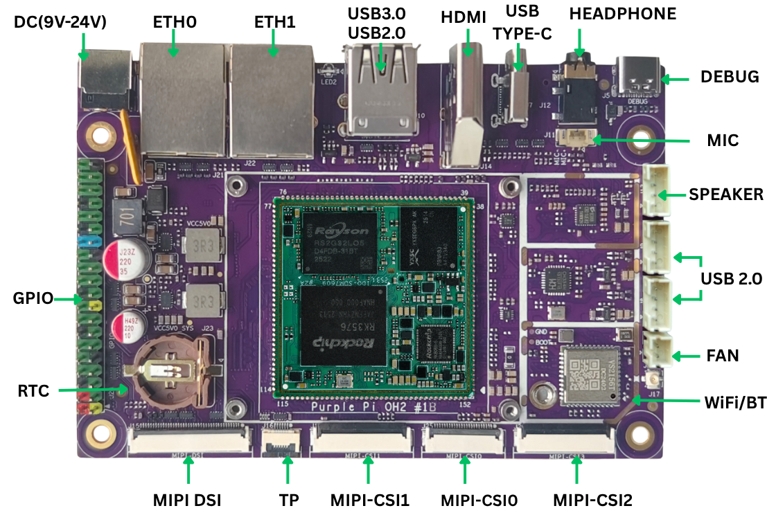
Back View
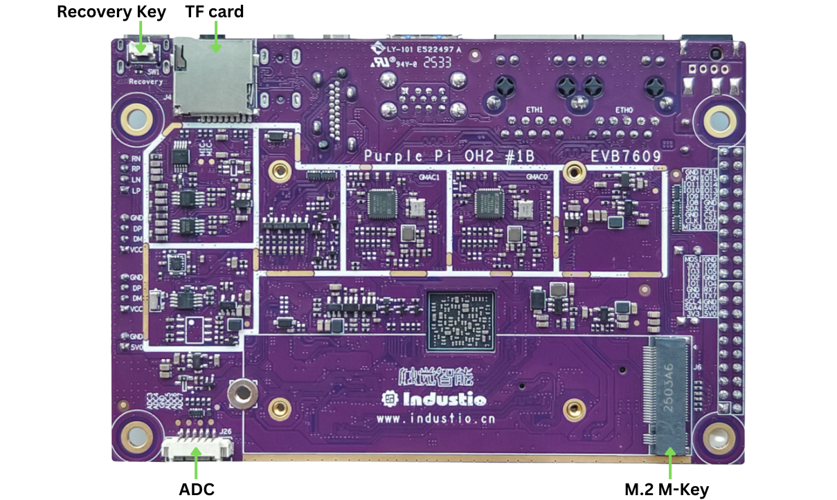
Technical Specifications
| Processor & Memory | |
|---|---|
| SoC | Rockchip RK3576 (8nm) |
| CPU | 4× Cortex-A72 @ 2.2GHz + 4× Cortex-A53 |
| NPU | 6 TOPS neural processing unit |
| RAM | Up to 16GB LPDDR4 |
| Storage | |
| eMMC | Onboard eMMC 5.1 (OS bootable) |
| microSD | TF card slot — SDIO 3.0 (J4) |
| M.2 NVMe | M-Key 2280, PCIe 2.1 (J6) |
| Display Output | |
| HDMI | HDMI 2.1 — up to 8K@60fps (J14) |
| DisplayPort | DP 1.4 via USB-C — up to 4K@30fps (J7) |
| MIPI DSI | 40-pin FPC 0.5mm connector (J15) |
| Camera Input | |
| MIPI CSI | 3× independent interfaces (J19, J20, J25) |
| Connectivity | |
| Ethernet | 2× Gigabit RJ45 (eth0: J21, eth1: J22) |
| WiFi / BT | AP6256 module (antenna FPC included) |
| USB 3.2 Gen1 | 1× Type-C OTG + DP Alt Mode (J7) |
| USB 3.0 | 2× Type-A stacked (J10) |
| USB 2.0 | 2× PH2.0-4P headers (J8, J9) |
| Expansion (40-pin Header) | |
| GPIO | 16× programmable GPIOs |
| UART | 3× TTL UART channels |
| I2C | 2× channels (I2C4: pins 3/5 · I2C7: pins 27/28) |
| SPI | 1× channel (/dev/spidev0.x) |
| CAN Bus | 2× CAN channels |
| ADC | 1× analog input header (J26) |
| Audio | |
| Codec | ES8388 |
| Speaker | PH2.0-4P dual channel, 4Ω 3W/ch (J13) |
| Headphone | 3.5mm 4-pole CTIA jack (J12) |
| Microphone | MX1.25T-2P connector (J11) |
| Other | |
| Debug UART | USB-C (CH340 chip, J5) at 1.5Mbps |
| RTC | Battery holder for CR1220 coin cell (J23) |
| Fan | PH2.0-2P 5V fan header (J3) |
| Power & OS | |
| Input Voltage | DC 9–24V (barrel jack) |
| Supported OS | Debian · Ubuntu · Buildroot |
Connectivity
Ethernet
The Purple Pi OH2 has two native Gigabit Ethernet ports (eth0 and eth1). Both support automatic DHCP — just plug in a cable and the board is network-ready.
# Check IP address assigned by DHCP
ip addr show eth0

# Set a static IP
nmcli con mod "Wired connection 1" ipv4.addresses 192.168.1.100/24 \
  ipv4.gateway 192.168.1.1 ipv4.dns "8.8.8.8" ipv4.method manual
nmcli con up "Wired connection 1"
WiFi
# Check interface status
nmcli device

# List available networks
nmcli device wifi list

# Connect to a network
nmcli device wifi connect "YourSSID" password "YourPassword"

# Confirm connection
nmcli connection show --active
ip addr show wlan0
Antenna required
Always connect the included WiFi/BT antenna FPC for reliable wireless reception.
Bluetooth
bluetoothctl power on          # Turn on Bluetooth
bluetoothctl scan on           # Scan for devices
bluetoothctl devices           # List found devices
bluetoothctl trust  XX:XX:XX:XX:XX:XX   # Trust a device
bluetoothctl pair   XX:XX:XX:XX:XX:XX   # Pair
bluetoothctl connect XX:XX:XX:XX:XX:XX  # Connect
GPIO (40-pin Header)
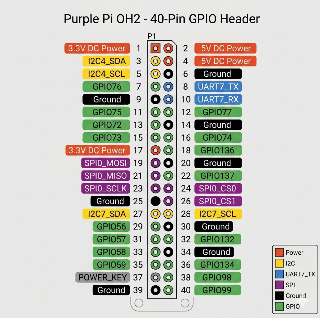
The 40-pin header is Raspberry Pi HAT-compatible and exposes 16 GPIOs, UART, I2C, SPI, and CAN. All GPIO logic is 3.3V.
# Install GPIO tools
sudo apt update && sudo apt install -y libgpiod-dev gpiod

# Set pin HIGH (Pin 7 = GPIO2_B4 = gpiochip2 offset 12)
gpioset gpiochip2 12=1

# Set pin LOW
gpioset gpiochip2 12=0

# Read a pin
gpioget gpiochip2 12

# Control multiple pins at once
gpioset gpiochip2 12=1 13=0 14=1
Key pin assignments
| Pin | Function | Device Node |
|---|---|---|
| 3 / 5 | I2C4 SDA / SCL | /dev/i2c-4 |
| 8 / 10 | UART7 TX / RX | /dev/ttyS7 |
| 19, 21, 23, 24, 26 | SPI0 (MOSI, MISO, CLK, CS0, CS1) | /dev/spidev0.x |
| 27 / 28 | I2C7 SDA / SCL | /dev/i2c-7 |
| 37 | POWER_KEY | /dev/input/event0 |
Storage & Expansion
M.2 NVMe SSD
Install a 2280 NVMe drive into the M-Key slot (J6), then verify detection:
microSD Card
The TF card slot (J4, back of board) supports SDIO 3.0. List storage after insertion:
Manual mount may be needed
During boot, eMMC partition changes can affect TF card automounting. Mount manually with mount /dev/mmcblk1p1 /mnt if needed.
USB Power Control
Software control for the two USB 3.0 Type-A ports:
echo 0 > /sys/class/leds/usb_pwr/brightness   # Power OFF
echo 1 > /sys/class/leds/usb_pwr/brightness   # Power ON
Camera (MIPI CSI)
Three independent MIPI CSI interfaces support simultaneous camera input.
| Connector | Device Node | Default Sensor |
|---|---|---|
| J19 | /dev/video42 | OV13855 |
| J20 | /dev/video51 | OV13855 |
| J25 | /dev/video33 | Standard CSI |
# Live preview from J19 (requires display)
export DISPLAY=:0
gst-launch-1.0 v4l2src device=/dev/video42 \
  ! video/x-raw,format=NV12,width=1920,height=1080,framerate=30/1 \
  ! videoconvert ! autovideosink sync=false

# Capture a still image from J19
v4l2-ctl --verbose -d /dev/video42 \
  --set-fmt-video=width=1920,height=1080,pixelformat='NV12' \
  --stream-mmap=4 --stream-skip=3 \
  --stream-to=./capture.yuv --stream-count=1 --stream-poll

# Play back the captured frame
ffplay -f rawvideo -video_size 1920x1080 -pixel_format nv12 ./capture.yuv
J20 color tint
J20 may show a green tint depending on the sensor module used. Apply a color correction filter in your pipeline if needed.
Audio
The ES8388 codec handles speaker, headphone, and microphone I/O.
# Enable speaker / headphone output
amixer -c 0 cset name='Speaker Switch' on

# Play audio
aplay -D hw:0,0 audio.wav

# Record from headphone mic (J12)
amixer -c 0 cset numid=67 off               # Disable onboard mic
echo -n "mic1" > /sys/class/es8388_mic/mic_channel
arecord -D hw:0,0 -f S16_LE -r 16000 -c 2 recording.wav

# Set capture volume (0–192)
amixer -c 0 cset numid=50 100

# Enable Automatic Level Control (stereo)
amixer -c 0 cset numid=41 3
Troubleshooting
| Issue | Likely Cause | Fix |
|---|---|---|
| No display on HDMI | Cable or resolution mismatch | Try a different HDMI cable; check OS display settings |
| WiFi weak or disconnects | Antenna not connected | Attach the included antenna FPC to the AP6256 connector |
| microSD not automounted | eMMC partition change on boot | Mount manually: mount /dev/mmcblk1p1 /mnt |
| NVMe not detected | Drive not fully seated | Re-seat the M.2 drive and re-tighten the screw |
| Camera shows green tint | Sensor color calibration on J20 | Apply color correction in GStreamer pipeline |
| No audio output | Speaker switch disabled | Run amixer -c 0 cset name='Speaker Switch' on |
| USB device not recognized | USB power is off | Run echo 1 > /sys/class/leds/usb_pwr/brightness |